Breadboarding: How to Go from Wiring to Debugging Breadboards
2025-12-29 | By Shruti Garg
Breadboards are the first step into getting into electronics. The easy, reusable, and convenient tool that allows you to try new ideas before getting into the depths of circuits. But breadboards can get tricky if you don’t properly understand how to debug them. Building them is the first thing, but then, from there, learning how to debug and understand the errors can take you a long way.
This post will teach you the depths of breadboarding, not just the surface level of inserting wires in various slots. I will show you how to troubleshoot, test, and organize your breadboard projects. The real learning is when something doesn’t work, and you use trial and error to fix it.
When I built my first breadboard circuit, a simple LED and resistor combo, I expected the breadboard to instantly work; however, nothing happened. No light turned on. That’s when I realized I had to think deeper into what the issue could be, such as:
- Is the LED inserted with the correct polarity?
- Is the resistor in the correct row that I need?
- Are the rails connected properly?
- After asking myself these questions, I realized that there isn’t always a clean-cut answer in electronics.
- We must learn to be patient and push ourselves to dig deeper when something is not working.
Here is a tutorial on building a simple LED switch circuit:
Let’s start with a small, testable circuit you can use to practice debugging.
You’ll need:
- 1× LED (any color you’d like)
- 1× 470 Ω resistor
- 1× SPST slide or tactile switch
- Breadboard
- Jumper wires
- 5 V power source (or 3.3 V, either one works)
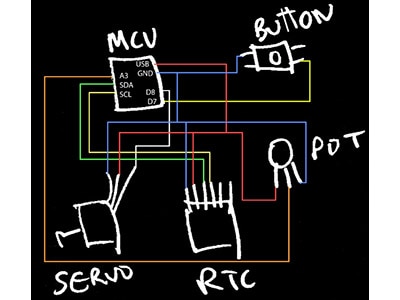
How to put the pieces together:
- Power setup: Connect your red rail to +5 V and the blue rail to ground.
- LED placement: Plug the LED so its long leg (anode) sits on one row and the short leg (cathode) on another.
- Resistor: Connect one end of the resistor to the anode row and the other to +5 V.
- Switch: Insert the switch so it bridges the cathode’s row to ground when pressed.
- Power up: Press the switch, and your LED should glow.
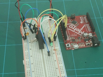
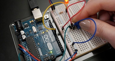
An image of how the breadboard should look:

As simple as this sounds, your light may not turn on. This is where you start debugging and checking if everything is correctly placed:
Some things to look out for are:

To confirm voltages, you can use a multimeter to check.
Good breadboarding habits to adopt:
- Color code your wires:
- For example: Use red for power, black for ground, and others for signal lines. This allows you to make your breadboard easily readable and easier to debug
- Keep your wires short; if you use long wires, things can get messy and hard to work with
- Label your workspace:
- Section off your workspace with different parts to organize your circuits, so that your board doesn’t get too crowded
- Don’t assume both the power rails are connected; you may need to bridge them yourself; many boards are split
- Double-check all your connections:
- One misplaced lead can make the biggest difference in the LED light, so make sure everything is properly connected
Last step:
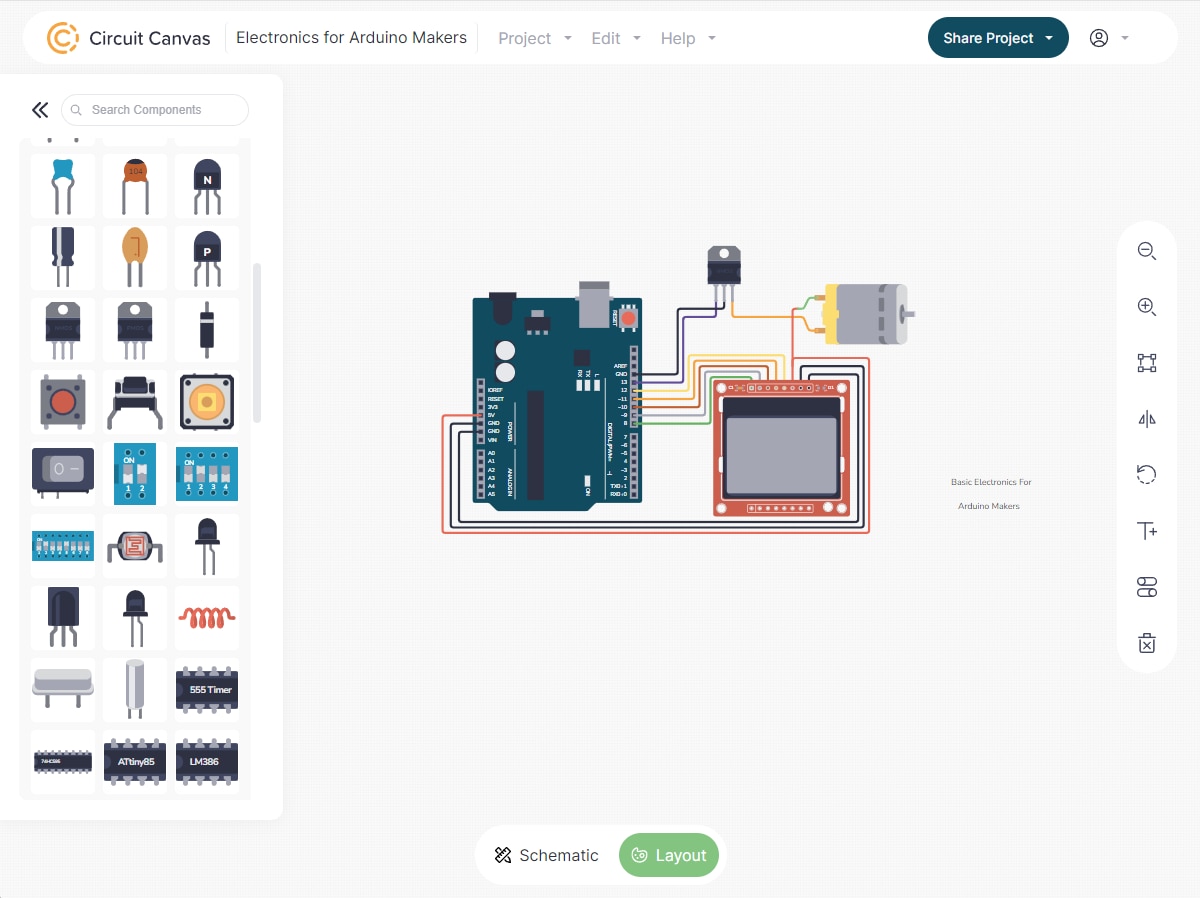
Once your LED-switch circuit works, try swapping the switch for a photo-resistor (LDR). Now your LED will glow brighter or dimmer depending on the light intensity.
For even more complex upgrades, you can use a transistor to amplify current so you can use multiple LEDS, scaling your simple breadboard projects to more complex ones.